I3CBlaster
Raspberry pico / RP2040 based USB to I3C converter with Python support
Install / Use
/learn @xyphro/I3CBlasterREADME
Download the I3CBlaster# I3CBlaster
What is I3CBlaster?
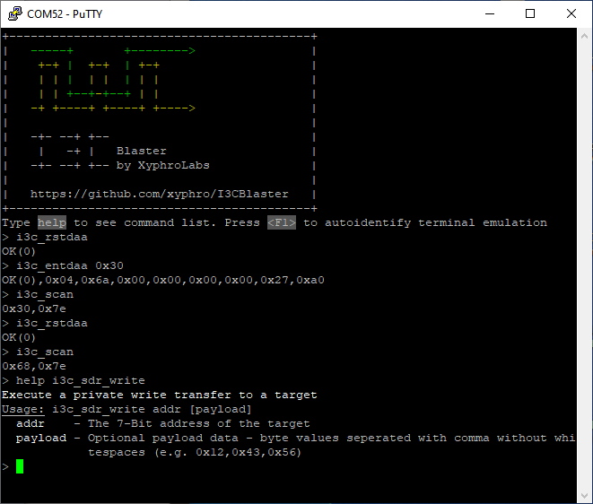
I3C Blaster is a firmware image you can flash to your Raspberry PI PICO board to let it act as USB to I3C converter. Simply add 2 pullup resistors and you are ready to go.
I3CBlaster has 3 usage schemes:
- Interactive using a terminal program like Tera-term or Putty
- From a Python program running on PC
To automate any tests, or building your own GUIs, ... A powerful feature here is, that it has an autoidentification scheme to detect the COM port number automatically. No need to struggle with which of your 20 COM ports is from the I3CBlaster device :smiley: - Need I3C in your on RP2040 C projects? Also possible, just integrate the i3c_hl module and you are good to go!
November 2025 update
In this Webinar I explain a bit the basics and usage of I3CBlaster. It is also a nice watch to get an introduction to I3C in general.
(click to watch)
Right before New-Year 2025 update
HDR-DDR transfers got added :sunglasses:
I only have V1.0 HDR-DDR capable target devices, so testing focused on that. But all aspects from V1.1 were also added. In case you start looking into HDR-DDR first time, please look into ENDXFER CCC documentation and i3c_ddr_config function, as quite some extensions were introduced in V1.1 spec version. Whenever I get access to a V1.1 capable target, I'll extend my testing.
Next planned step before doing further SW extensions is a level translator hardware and extension of the binary to the tiny <a href="https://www.seeedstudio.com/XIAO-RP2040-v1-0-p-5026.html" target="_blank">Seeedstudio Xiao RP2040 boards</a>.
In need of an I3C Analyzer?
Have a look at my I3C daughter project, which is a Saleae Logic Analyzer plugin to decode I3C OD, I3C SDR and I3C HDR-DDR transfers: <a href="https://github.com/xyphro/XyphroLabs-I3C-Saleae-Protocol-Analyzer" target="_blank">https://github.com/xyphro/XyphroLabs-I3C-Saleae-Protocol-Analyzer</a>
Do you want to decode I3C with Sigrok Pulseview?
Have a look at my I3C decoder project for Sigrok Pulseview:
<a href="https://github.com/xyphro/Sigrok-I3C-decoder" target="_blank">https://github.com/xyphro/Sigrok-I3C-decoder</a>
What else is this?
It is an I3C controller driver code based on a single RP2040 PIO. Feel free to reuse it in other projects! The i3c_hl.c or .h files provide an interface to all kind of different I3C transfer types.
To include it in your projects as a module, simply use i3c_hl.h i3c_hl.c and i3c.pio. i3c_hl.h exposes all the i3c API functions for the i3c driver. But don't forget credits - this project took lots of late night work to make it work well :-)
Why did I develop I3CBlaster?
Because so far there is no easy and low $ solution available to learn I3C protocol or evaluate I3C target devices in the market. Having the ability to execute I3C transfers was for me also a major step in understanding the I3C protocol and its many exceptions and hidden features and the reasons behind them.
level translator board
![]()
[25th August 25]
Finally i did it and added i2c functions. They are added to uart terminal, but also exposed consistently via python layer.
The new functions are:
  i2c_clk                  - Set I2C clock frequency
  i2c_scan                 - Scan for available i2c addreses. Reserved I2C addre
                             sses (like 0x00) are not scanned
  i2c_timeout              - Set I2C timeout value. The timeout applies to read&
                             write and the whole transfer time. The default time
                             out is 100ms
  i2c_write                - Execute an i2c write transfer to a target
  i2c_read                 - Execute an i2c read from a target
  i2c_writeread            - Execute an i2c combined write read transfer from a
                             target
[1st February 25] I added a level translator board for the XIAO module and adjusted software to use it. The Kicad design can be found here: <a href="https://github.com/xyphro/I3CBlaster/tree/main/hw">/hw</a>
If you want to investigate the schematic you can look here: <a href="https://raw.githubusercontent.com/xyphro/I3CBlaster/master/hw/schematic_LevelTranslatorXiaoRp2040.pdf">hw/schematic_LevelTranslatorXiaoRp2040.pdf</a>
The schematic shows also some measurement results of the board, focused on propagation delay. I am not yet happy about the propagation delays for 1.0V and 1.2V and you might need to slow down the I3C clock frequency a bit, but this is a first starting point.
The functional supported IO voltage levels are to 0.9V 3.6V.
The 3D case is to be released after improving the design a bit for better snap fit of the 2 halves and fixing the pinning order labels.
The edge acceleration function can be turned on and off by setting GPIO0 to either 0 (off) or to 1 (on). The gpio_write function can be used for that sake:
gpio_write 0 0to turn it off.gpio_write 0 1to turn it on (=default state).
Software side updates: The software auto detects now if it runs on a XIAO RP2040 board or a Raspberry pi PICO.
When running it on the Xiao module, the I3C signal pinning is:
| Module name | SCL | SDA | |----------------|----------------|----------------| | Raspberry Pi Pico | GPIO17 | GPIO16| | Seeed Xiao RP2040 | GPIO7 | GPIO6|
The Xiao RP2040 module has a nice NeoPixel LED. I enabled it to show in the software some states.
| LED color | Explanation | |-----------|-------------| |RED | The Vtarget voltage is not supplied to the Vtarget pin | |GREEN | The supplied target voltage is >= 0.9V. note that the voltage level changes "how bright" the LED will glow GREEN| |BLUE | Whenever data is received over the serial port, the led will flash BLUE to show activity |

Further planned changes
Upcoming SW changes will include functional extensions, but first an instantiation method to enable running the i3c_hl module 2 I3C controllers on RP2040 on both PIO instances, but also a cleanup and Doxygen style API documentation.
What is the difference to commercial products?
A bitbanged or here HW supported bitbanged I3C master will never get exactly to the percentage of bus utilization of a real HW I3C master. While the implementation was targeted to be efficient here, there are phases where a PIO statemachine to CPU interaction will "pause" the bus for short times, especially for HDR-DDR transfers. The peak i3c clock frequency of 12.5MHz is reached in this solution. Have a look at the demo code section below to download a captured waveform which allows you to zoom into the timing details. Note, that those pauses are ensured to occur in phases where SCL is low, such that the I3C timings are not violated, which is important for mixed bus scenarios.
A bitbanged solution like the one here can enable you to modify its code for failure insertion to test the robustness of a target. E.g. you can send a wrong CRC value or parity on purpose, generate unexpected bus conditions, etc.
So it might not be an exact 100% replacement of commercial tools, but can be a good step for very initial tests/protocol investigation or later extension with failure insertion methods.
The USB interface is here a CDC based UART, as delivered by Raspberry PI SDK. This solution is a bit inefficient compared to a dedicated custom solution, but enables maximum usability and extendability for the community.
What is I3C?
I3C is a successor protocol based on I2C, but enabling higher transfer rates. It pulled in many mechanisms from the less well known i2c speed modes 3.4MHz (HS), 5 MHz or 10 MHZ. There are multiple transfer modes defined using SDR push-pull mode transfers, 2 different kinds of DDR modes are part of the public BASIC I3C specification. The full I3C specification even has multi lane support included enabling transfer rates over 100MBit/s and 2 flavors of called ternary modes where also the clock line is used to transfer data.
It maintains in a limited way compatibility to the I2C protocol. This legacy support simplifies the learning curve for new users, but creates complexity in the overall protocol definition.
Clock stretching devices, Multi master arbitration are not supported, a maximum of about 5 I2C devices on a single bus segment are the most dominant limitations for i2c usage on i3c busses.
It is also feasible to connect i2c and i3c devices on the same bus with limitations on max. capacitive load (50pF / 100pF) or max. datarate. Similar to i2c a degradation of the i2c clock frequency to cope with higher capacitive load is possible as function of drive strength.
Another very useful feature of I3C is the realization of the so called IBI feature: In-Band-Interrupts. I3C target devices have now the capability to raise an interrupt over the same 2 wires where it communicates with. There are 2 schemes implemented - one when the bus is busy and arbitration based scheme and another one when the bus is idle. The IBI features is easy to understand from bus perspective, but can cause a bit of headaches for SW stacks due to out-of context occurrence within the same communication channel.
Note that according to I3C protocol definition the IBI feature only works in SDR transfer mode, so whenever HDR modes are used and an IBI feature is required ensure to transition after transfers back to SDR mode with an HDR Exit condition.
Some resources:
|Name |Link | |----------------|----------------| | Public I3C Basic spec | https://www.mipi.org/mipi-i3c-bas
Related Skills
openhue
354.3kControl Philips Hue lights and scenes via the OpenHue CLI.
sag
354.3kElevenLabs text-to-speech with mac-style say UX.
weather
354.3kGet current weather and forecasts via wttr.in or Open-Meteo
casdoor
13.3kAn open-source AI-first Identity and Access Management (IAM) /AI MCP & agent gateway and auth server with web UI supporting OpenClaw, MCP, OAuth, OIDC, SAML, CAS, LDAP, SCIM, WebAuthn, TOTP, MFA, Face ID, Google Workspace, Azure AD
