CANFDuino
No description available
Install / Use
/learn @togglebit/CANFDuinoREADME
CANFDuino

Intro
CANFDuino is the best platform for open source CAN bus Arduino projects. It combines several essential features into one complete "ready-to-modify" package for the real world, including dual CANFD bus ports, SD card slot, and a multitude of analog/digital IO. It also includes a built-in prototyping shield for SMT and through-hole parts, and rugged packaging and connections.
Hardware Hookups
For making connections the hookup guide is here: https://togglebit.net/canfduino-hookup-guide/
Installing the Library and First Sketch
The following are steps for installing and testing CANFDuino support for the Arduino IDE (UPDATE tested 2.2.1), running and testing your first CAN sketch:
Note this content can also be found here https://togglebit.net/getting-started-with-canfduino/
Step 1. - Download the entie codebase, un-zip it. Rename "CANFDuino-master" to "CANFDuino".
Step 2. - Close the Arduino IDE if you have it open. Copy the whole "CANFDuino" folder to your local arduino hardware folder. The path for this hardware folder is: C:\Users\YOUR USERNAME\Documents\Arduino\hardware. The whole folder should be pasted directly into the hardware folder creating: C:\Users\YOUR USERNAME\Documents\Arduino\hardware\CANFDuino. If you do not have a hardware folder, create one and place CANFDuino folder inside of it.
Step 3. - Open the Arduino IDE, Go to the "Tools->Board->CANFDuino" to select the CANFDuino board as your target board. (If you have a CANFDuino based upon the SAMC21G17A processor, choose "CANFDuino17A" failing to do so may result in unsupported device message)
Step 4. - Go to Tools->Board->-Boards Manager-Wait for the downloads to finish. Click on “Arduino SAMD Boards (32-bits ARM Cortex-M3), including Arduino M0” and Install. This can take a while to download if you don't already have the library.
Step 5. - Go to File->Examples->CANFDuino->CANFDuino_Test500Kb.ino (have a look at all the other examples as well)
Step 6. - Wire the CANbus DB9 connectors or jump the 2pin headers on the PCB to connect CAN0 bus to the CAN1 bus. CAN0 High->CAN1 High, CAN0 Low->CAN1 Low.
Step 7. - Jumper at least one of the two termination resistors on the PCB enabling termnination resistors on the bus. (two ideally)
Step 8. - Connect USB cable to CANFDuino and the PC, this will power the unit an prompt for a dirver install. Wait for the driver to install if needed (one option is to skip obtaining from Windows and selecting the driver in the hardware\samd\drivers folder). Go to Tools->Port and select the COMM port that is labled CANFDuino. You may need to shut down the IDE and re-open it after installing the driver. (if needed, use FTDI exe in this repository to install driver, see link below for mac)
Step 9. - Go to Sketch->Upload. After compiling the IDE will send a signal to the CANFDuino to enter the bootloader. Note when the unit is bootloading the orange LED will stay on and strobe off quickly for 1-2 seconds. This occurs anytime the processor is reset (initial power on etc). You should see the green/red comms LED's flicker during sketch upload.
Step 10. - Go to Tools->Serial Monitor, note that this will also cause entry into bootloader for about 4-5 seconds before the sketch runs (for permanant code/bootloader bypass there is a jumper on the PCB).
Step 11. - See diagnostic printout in the comms window indicating pass/fail of testing. Typically the cause of failure is improper wiring or no termination resistor.
Ubuntu Flashing
- download: https://www.mattairtech.com/software/arduino/Bossa-1.7.0-mattairtech-2-x86_64-linux-gnu.tar.gz
or try the bossac executable here for Linux x86:
https://github.com/togglebit/CANFDuino/tree/master/tools/bossac
-
Extract and copy bossac and other binaries to installation path of bossac CANFDUINO Arduino Studio project path - cp -r * /home/disdi/Downloads/arduino-1.8.14/hardware/CANFDuino/tools/bossac/CANFDuinoBossac/
-
Flash the binary directly or via Arduno IDE sudo bossac --port=ttyUSB0 -e -w -v -b /tmp/CANFDuino_Test500kb.ino.CANFDuino.bin
Mac Flashing
-
Make sure the mac FTDI driver https://ftdichip.com/drivers/vcp-drivers/ is installed to recognize the device, the one included in this repo is for Windows.
-
Download the bossac programming utility https://github.com/shumatech/BOSSA/releases for mac and replace in the path C:\Users\PC\Documents\Arduino\hardware\CANFDuino\tools\bossac\CANFDuinoBossac.
Example Code
All example sketches are found here. If you have followed the instructions above, all of the examples below are found locally on your machine in the C:\Users\YOUR USERNAME\Documents\Arduino\hardware\CANFDuino\samd\libraries\CANFDuino folder. This can also be accessed in the IDE by going to File->Examples->CANFDuino->.
CAN Packet Monitoring
CANFduino_SavvyCAN.ino

SavvyCAN is the awesome open source CAN bus tool developed by Collin Kidder. Programing the CANFDuino with this sketch will make it emulate an Arduino DUE board that is supported by SavvyCAN. This sketch has been tested for sniffing and transmission on both ports, with all settings getting saved into flash.
Steps for using SavvyCAN with CANFduino
Step 1. - Do everything above in getting started section to make sure yoru hardware works. Hook up the CAN/FD ports to the buss(es) you want to monitor.
Step 2. - Open ArduinoIDE, go to File->Examples->CANFDuino_SavvyCAN.ino
Step 3. - Upload it with the IDE and once complete place a jumper on "NO BOOT" pin to bypass the bootloader when the device is reset.
Step 4. - Download and install SavvyCAN for your platform. Watch Youtube videos on how to use SavvyCAN.
Step 5. - In SavvyCAN open the connection window, click "add new device connection" select "serial connection" you should see a COM port present corresponding to the CANFduino, click "create new connection".
Step 6. - From the connections settings window, select "enable console" to see the serial traffic including the heartbeat.
Step 7. - For CAN0 and CAN1 shown in the bottom tabs select "enable bus" and select the baud rate you wish to monitor from the drop down list.
Step 8. - Select "reset selected device" to reset the CANFDuino with the new baud rates. The baud rates will now be remembered and you do not need to reprogram the device each time you want to use SavvyCAN. If you are connected to a bus, you should see packets coming in the serial window, close this window to see the bus traffic in the main window.
Step 9. - If you have not connected to a bus, remember to set your termination jumpers on the CANFDuino, see the wiring guide here
When in doubt, power all other devices on the network down, open the connection window, make sure the bus is enabled, watch the serial console, and reset the device if needed (e.g. CAN bus goes into bus off state).
For a CANFD bus, use these steps
Step 1. - Do everything above in getting started section to make sure yoru hardware works. Hook up the CAN/FD ports to the buss(es) you want to monitor.
Step 2. - Open ArduinoIDE, go to File->Examples->CANFDuino_SavvyCANFD.ino
Step 3. - Upload it with the IDE and once complete place a jumper on "NO BOOT" pin to bypass the bootloader when the device is reset.
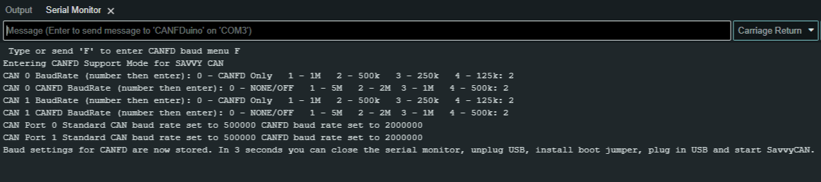
OPTIONAL: - We did build in a terminal interface for configuring the baud rates for CANFD and traditional CAN. If you want to pre-configure your unit before connecting to SavvyCAN, do NOT place the jumper on the NO BOOT pin and open up the serial monitor window in the ArduinoIDE with a 2MB serial port baud rate, and "carriage return" when pressing enter. Follow the on-screen prompts and type your responses (should only be a single number) followed by the return key until all of the baud rates are set. Now place the "NO BOOT" jumper on and power cycle (unplug USB, plug back in). See below, 2,2,2,2 results in both ports set for 500k/2MB CANFD. This does enable FD rates beyond 2MB.
Step 4. - Download our forked version of SavvyCAN from GitHub (Windows supported only right now). The entire codebase can be downloaded, with the windows executable located in the "release" folder. Additionally, you can watch Youtube videos on how to use SavvyCAN.
Step 5. -In SavvyCAN open the connection window, “Click Add New Device Connection”, select “enable console” to see the serial traffic including the heartbeat, click select “serial connection” and you should see a COM port present corresponding to the CANFduino, select “CAN-FD” checkbox then click “create new connection“. You should see messages confirming data tx/rx over the serial port in the console window. If you precofigured your baud rates and port settings in the Arduino IDE they will appear here. If there are no bau rate sttings, for CAN0 and CAN1 shown in the bottom tabs select “enable bus”, “enable CANFD” and select the standa”rd CAN “speed” and CANFD “baud rate” you wish to monitor from the drop down list. For each bus tab, click”save bus settings” (remember do this for both tabs after you set the bauds etc)
