Vsdstdcelldesign
This repository contains all the information needed to run RTL2GDSII flow using openlane flow. Apart from that, it also contain procedures on how to create a custom LEF file and plugging it into an openlane flow.
Install / Use
/learn @nickson-jose/VsdstdcelldesignREADME
Standard cell design and characterization using openlane flow
This repository contains all the information needed to build and run openlane flow, which has the capability to perform full ASIC implementation steps from RTL to GDSII. In addition, it also contains procedures on how to create a custom LEF file and plugging it into an openlane flow.
Table of Contents
- Introduction to Openlane flow.
- Overview of Physical Design flow.
- Build and invoke openlane.
- Introduction to LEF.
- Standard cell design and characterization in openlane.
- Future work.
- Limitations.
- Acknowledgements.
Introduction to Openlane flow
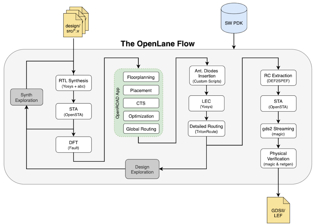
OpenLANE is a completely automated RTL to GDSII flow which embeds in it different opensource tools, namely, OpenROAD, Yosys, ABC, Magic etc., apart from many custom methodology scripts for design exploration and optimization. Openlane is built around Skywater 130nm process node and is capable of performing full ASIC implementation steps from RTL all the way down to GDSII. The flow-chart below gives a better picture of openlane flow as a whole (Image Courtesy: efabless/openlane)
Overview of Physical Design flow
Place and Route (PnR) is the core of any ASIC implementation and Openlane flow integrates into it several key open source tools which perform each of the respective stages of PnR. Below are the stages and the respective tools (in ( )) that are called by openlane for the functionalities as described:
- Synthesis
- Floorplanning
- Placement
- Clock Tree Synthesis (CTS)
- Synthesizing the clock tree (TritonCTS).
- Routing
- Performing global routing to generate a guide file for the detailed router (FastRoute).
- Performing detailed routing (TritonRoute)
- GDSII Generation
- Streaming out the final GDSII layout file from the routed def (Magic).
Build and Invoke openlane
Detailed description on how to build and invoke openlane is given in this link.
Introduction to LEF
For a PnR tool to correctly place and route a block (a macro or a std. cell), it doesn't need to know entire layout information of the block; just the pin positions, PR boundary is sufficient. These minimal and abstracted information is provided to the tool by the Library Exchange Format (LEF) file. LEF file also serves the purpose of protecting intellectual property and is basically of two types:
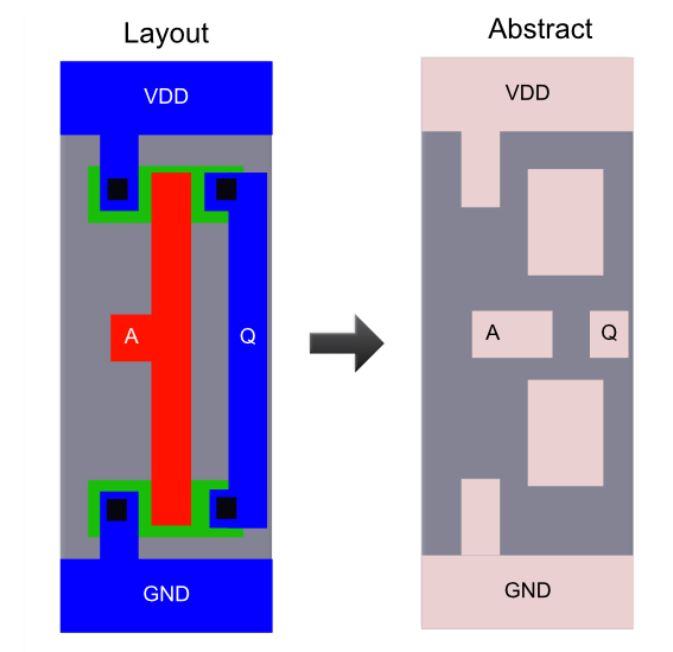
- Cell LEF - It's an abstract view of the cell and only gives information about PR boundary, pin position and metal layer information of the cell.
- Technology LEF - It contains information about available metal layer, via information, DRCs of particular technology used by placer and router etc.. The below diagram highlights the difference between a layout and a LEF (Image Courtesy: Google):
Standard cell design and characterization in openlane
Objective
The goal of the project is to design a single height standard cell and plug this custom cell into a more complex design and perform it's PnR in the openlane flow. The standard cell chosen is a basic CMOS inverter and the design into which it's plugged into is a pre-built picorv32a core.
About PicoRV32
PicoRV32 is a CPU core that implements the RISC-V RV32IMC Instruction Set. It can be configured as RV32I, RV32IC, RV32IM, or RV32IMC core; where the suffixes stand for:
- M - Multiply extension
- I - Base Integer Instructions
- C - Compressed Instructions
PicoRV32 is free and open hardware licensed under the ISC license. All features and data-sheet related to picoRV32 core can be obtained here.
Standard cell layout design in Magic
-
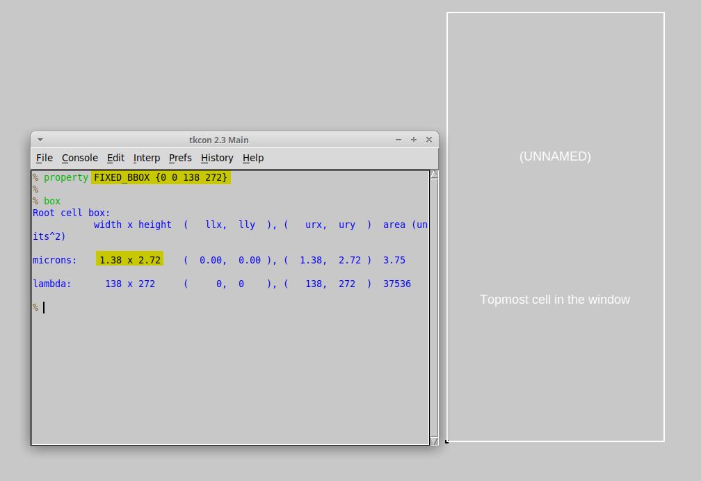
The proposed inverter for the design is a single height standard cell, so the dimensions needs to be a multiple of the single height place site; which for sky130 node has a nomenclature of
unithdwith dimensions(in microns): 0.46 x 2.72 (width x height) for sky130_fd_sc_hd PDK variant. The magic tool is invoked with sky130 tech file asmagic -T sky130A.tech &(the magic tech file (sky130A.tech) has also been included in this repo under/libsas reference). -
Thus, the first step in magic layout tool is to create a bounding box with a width of 1.38 (3 x width(unithd)) and height of 2.72. This can be done by using command
property FIXED_BBOX {0 0 138 272}in magic tkcon window.
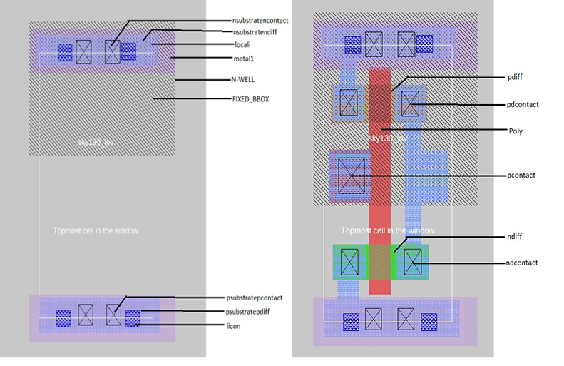
- This is followed by defining the ground and power segments (in metal 1), the respective contacts and finally the layout of the logic part. Same procedure can be followed for any standard cell layout.
Note:
The layout (also included as the part of this repo, viz., sky130_inv.mag) can be viewed in magic layout window as magic -T sky130A.tech sky130_inv.mag &
Create port definition
Once the layout is ready, the next step is extracting LEF file for the cell. However, certain properties and definitions need to be set to the pins of the cell which aid the placer and router tool. For LEF files, a cell that contains ports is written as a macro cell, and the ports are the declared PINs of the macro. Our objective is to extract LEF from a given layout (here of a simple CMOS inverter) in standard format. Defining port and setting correct class and use attributes to each port is the first step. The easiest way to define a port is through Magic Layout window and following are the steps:
- In Magic Layout window, first source the .mag file for the design (here inverter). Then Edit >> Text which opens up a dialogue box.
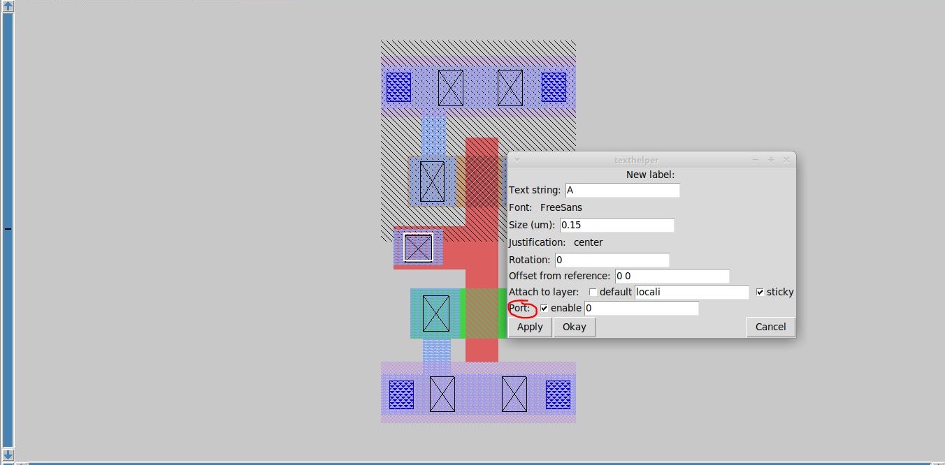
- For each layer (to be turned into port), make a box on that particular layer and input a label name along with a sticky label of the layer name with which the port needs to be associated. Ensure the Port enable checkbox is checked and default checkbox is unchecked as shown in the figure:
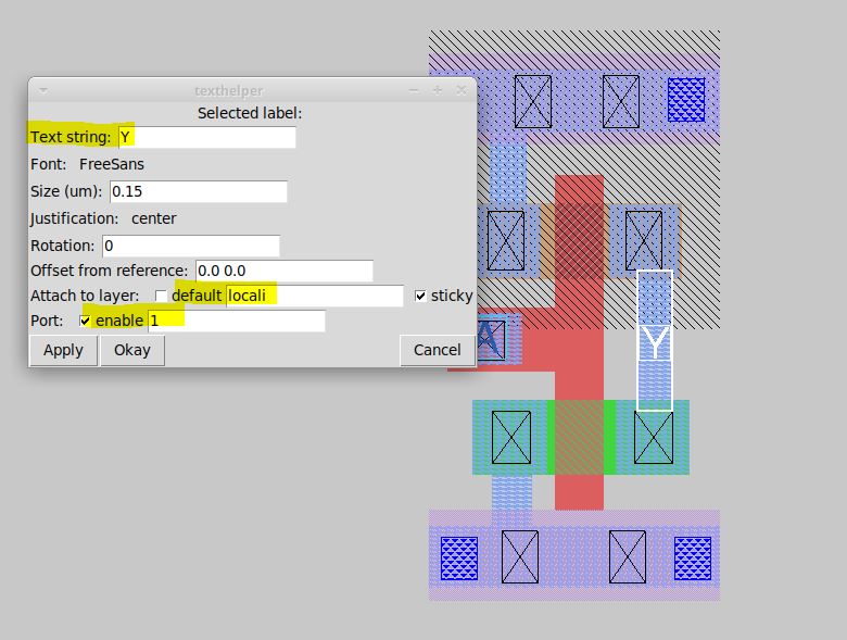
In the above two figures, port A (input port) and port Y (output port) are taken from locali (local interconnect) layer. Also, the number in the textarea near enable checkbox defines the order in which the ports will be written in LEF file (0 being the first).
- For power and ground layers, the definition could be same or different than the signal layer. Here, ground and power connectivity are taken from metal1 (Notice the sticky label)
| VPWR | VGND |
| --------------------------------------------------------------------------------------------| ------------- |
| 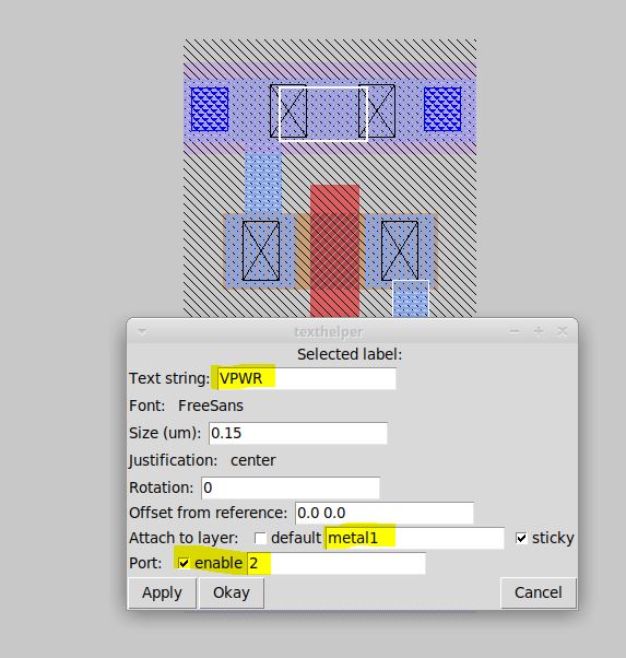 |
| 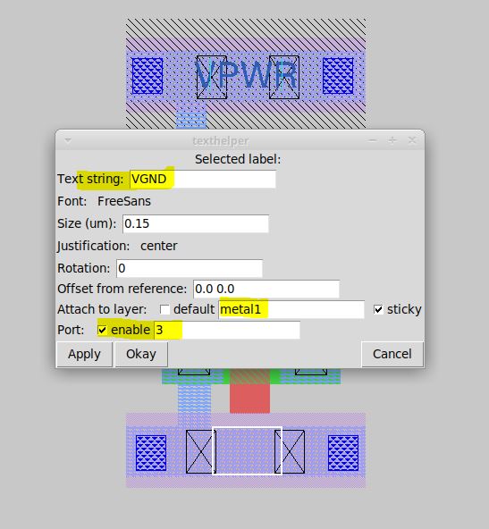 |
|
Set port class and port use attributes for a layout
Post port definition, the next step is setting port class and port use attributes. The "class" and "use" properties of the port have no internal meaning to magic but are used by the LEF and DEF format read and write routines, and match the LEF/DEF CLASS and USE properties for macro cell pins. Valid classes are: default, input, output, tristate, bidirectional, inout, feedthrough, and feedthru. Valid uses are: default, analog, signal, digital, power, ground, and clock. These attributes are set in tkcon window (after selecting each port on layout window. A keyboard shortcut would be repeatedly pressing s till that port gets hig
Related Skills
clearshot
Structured screenshot analysis for UI implementation and critique. Analyzes every UI screenshot with a 5×5 spatial grid, full element inventory, and design system extraction — facts and taste together, every time. Escalates to full implementation blueprint when building. Trigger on any digital interface image file (png, jpg, gif, webp — websites, apps, dashboards, mockups, wireframes) or commands like 'analyse this screenshot,' 'rebuild this,' 'match this design,' 'clone this.' Skip for non-UI images (photos, memes, charts) unless the user explicitly wants to build a UI from them. Does NOT trigger on HTML source code, CSS, SVGs, or any code pasted as text.
openpencil
2.1kThe world's first open-source AI-native vector design tool and the first to feature concurrent Agent Teams. Design-as-Code. Turn prompts into UI directly on the live canvas. A modern alternative to Pencil.
openpencil
2.1kThe world's first open-source AI-native vector design tool and the first to feature concurrent Agent Teams. Design-as-Code. Turn prompts into UI directly on the live canvas. A modern alternative to Pencil.
ui-ux-designer
Use this agent when you need to design, implement, or improve user interface components and user experience flows. Examples include: creating new pages or components, improving existing UI layouts, implementing responsive designs, optimizing user interactions, building forms or dashboards, analyzing existing UI through browser snapshots, or when you need to ensure UI components follow design system standards and shadcn/ui best practices.\n\n<example>\nContext: User needs to create a new dashboard page for team management.\nuser: "I need to create a team management dashboard where users can view team members, invite new members, and manage roles"\nassistant: "I'll use the ui-ux-designer agent to design and implement this dashboard with proper UX considerations, using shadcn/ui components and our design system tokens."\n</example>\n\n<example>\nContext: User wants to improve the user experience of an existing form.\nuser: "The signup form feels clunky and users are dropping off. Can you improve it?"\nassistant: "Let me use the ui-ux-designer agent to analyze the current form UX and implement improvements using our design system and shadcn/ui components."\n</example>\n\n<example>\nContext: User wants to evaluate and improve existing UI.\nuser: "Can you take a look at our pricing page and see how we can make it more appealing and user-friendly?"\nassistant: "I'll use the ui-ux-designer agent to take a snapshot of the current pricing page, analyze the UX against Notion-inspired design principles, and implement improvements using our design tokens."\n</example>
