MeshRemodel
Addon Workbench for FreeCAD, used to aid in manually remodeling mesh objects.
Install / Use
/learn @mwganson/MeshRemodelREADME
MeshRemodel Workbench
<img src="freecad/Mesh_Remodel/Resources/Icons/CreatePointsObject.svg" alt="icon"> <br/>Toolbar Icon
Download the <a href = "https://github.com/mwganson/MeshRemodel/blob/master/freecad/Mesh_Remodel/Resources/Icons/CreatePointsObject.svg">SVG Toolbar Icon</a><br/>
Installation
Can be installed via the AddonManager in Tools menu -> AddonManager. After restarting the AddonManager you should find MeshRemodel in the list of workbenches you can install. <br/>
Overview
Use this workbench to aid in remodeling imported mesh objects. The preferred workflow is to select the mesh, then click either create points object or create wireframe object. This creates an object with selectable points or edges at all of the mesh vertices or edges. Use the selectable points or edges to create Mesh Remodel elements, such as points, line segments, arcs, circles, or bsplines. You can then select those created elements and form a wire using the create a wire (Draft upgrade) tool, which wire can then be also upgraded to a face. The face can be used with Part Extrude, Part Sweep, Part Revolve, and Part Loft tools to create solids.<br/> <br/>
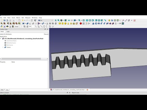
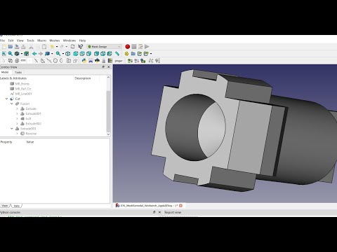
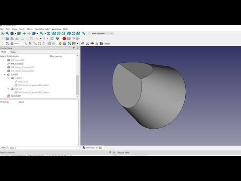
Links to Youtube Videos
 <br/>
<br/>
 <br/>
<br/>
 <br/>
<br/>
<br/>
<br/>
Create Points Object (mesh objects)
<img src="freecad/Mesh_Remodel/Resources/Icons/CreatePointsObject.svg" alt="create points object"><br/> Select the mesh object in the tree, then use this command to create a points object containing all the vertices of the selected mesh object. The points object is a compound consisting of Part Point (vertex) objects, one per vertex in the selected mesh. The purpose of this object is to provide selectable points in the 3d view. We can use these selectable points with the other tools in the workbench to create the lines, circles, arcs, and polygons needed to remodel the mesh. These can also be used in repairing meshes in conjunction with the remove point, move point, and add or remove facet tools.<br/> See also the Create WireFrame object, which can be used for the same purpose. Which to use is up to you, but I recommend using this Points object because it is much, much faster to recompute. Also, when adding facets to the mesh object, which is going to be the most common usage of the tool, you need to select points instead of edges anyway in order to better control the order of selection of the points, which is critical to the process. Edge selection, although a bit easier than vertex selection doesn't work as well for adding multiple consecutive facets.<br/> Tip: I have found when selecting the vertices to add a facet that if I select them in counter-clockwise fashion the facets created are more likely to have the proper normal orientation. <br/> If you hold Ctrl key down while invoking this command the mesh object will be made partially transparent and non-selectable in the 3d view. You can still select it in the tree view, but it will not appear to be selected in the 3d view and on mouse over you will not see it change to pre-select color. This will make it easier to see the MR_Points object. These settings can be changed in the mesh object's view tab in the property view. Even without Ctrl the mesh will be set to DisplayMode = "Flat Lines", so you can see how the points connect to make up the facets, and the Lighting property is set to "One side" so you can see if there are any flipped normals. <br/> Update: As of v1.82 you can now also create a points object from a Points cloud object created in Points workbench, which are non-selectable. So, if you need to be able to select the individual points in a points cloud use this tool to create the selected points object. Because the Points cloud object points are non-selectable the algorithm uses the first 3 points in the object to define the plane. If those 3 points are colinear then it won't work.<br/> <br/>
Create WireFrame Object (mesh objects)
<img src="freecad/Mesh_Remodel/Resources/Icons/CreateWireFrameObject.svg" alt="create wireframe object"><br/> Creates a parametric object based on Part::FeaturePython class from the selected mesh object. The lines and vertices of this object serve as a proxy for the lines and vertices of the mesh object, which are not selectable individually in FreeCAD. You select the edges and vertices of the proxy object and MeshRemodel will translate those selections into selections of the mesh object for the purposes of the various mesh repair tools available in MeshRemodel, including the move point too, the remove point too, and the add/remove facet tool. See also the Create Points Object command.<br/> <br/>
Mesh Boundary Wires (mesh objects)
<img src="freecad/Mesh_Remodel/Resources/Icons/MeshBoundaryWires.svg" alt="mesh boundary wires"><br/> Creates wires from the holes in a mesh. If a wire is planar, then a meshed face is also produced. This meshed face may be merged with the original mesh in the Mesh workbench to fill in the hole left after a mesh is trimmed with a plane in that workbench. The mesh will need to repaired after this merger because at the very least there will be some duplicated points that must be removed.<br/> This function is a good diagnostic tool to help find holes in a mesh that might not be evident upon a brief examination. It can also show defects that are difficult to find, such as where 2 points are very close to each other and the mesh has tiny facets that need to be fixed.
Move Point (mesh objects)
<img src="freecad/Mesh_Remodel/Resources/Icons/MovePoint.svg" alt="Move a point in a mesh object"><br/> This tool works on mesh objects. You need to create a points object or a wireframe object from the mesh first in order to have selectable points to work with. Select the mesh object and a point from the points object to be moved, then click the toolbar icon. You will get a dialog in which you can set the new coordinates for the point. The changes the mesh object, but you can use Undo to undo the changes.<br/> <img src="Resources/media/move_point_scr1.png" alt="move point screenshot"><br/> Notice in the above screenshot there is a red dot on the screen. This shows the new position of the point once you click OK. The Normal spinbox at the bottom of the dialog is used to move the point along its normal vector. If you change the Normal field it resets the other X, Y, and Z fields to their defaults, and then applies the calculations needed to move them in the point's normal direction by the amount specified in the Normal field. For Mesh objects the normal direction of a point is a direction outward from the mesh, calculated from the angles of the facets connected to that point. This value can be positive or negative, depending on which way you wish to move the point. Keep in mind this changes the mesh topology and could create issues, such as self-intersections or folds on surface. It's a good idea to check your mesh after adding the point with the Mesh workbench analyze tool. If moving the point has introduced defects to the mesh, then you have the option of using Undo to undo the changes.<br/> In addition to selecting a point and moving it via the dialog, you can also select 2 points. The first point selected is the point to be moved, and the second point is the destination. In this manner you can merge the 2 points together.<br/>
Remove Point (mesh objects)
<img src="freecad/Mesh_Remodel/Resources/Icons/RemovePoint.svg" alt="Remove a point"><br/> With this tool you can remove a point from (or add a new point to) a mesh. When the point is removed all of the facets connecting to it are also removed. Not to worry, it's fairly simple to add facets back to replace the ones that get removed by using the add facet tool, described below. If you don't want to lose the facets it might be possible to move the point to another point in the mesh instead. This will preserve the facets and bind them to the other point.<br/> To add a point you must first select an edge that already contains 2 points in the mesh. Then use Alt+Click to add the new point. This splits the facets that share the edge, creating 2 new facets at the picked point on the edge.<br/> Another way to add a new point is by adding a new facet with the add facet tool. The point to be added is a picked point you have selected that is not already part of the mesh when you add the new facet. Use the create point object command to add a new point to select or use a vertex of another object, such as a cube.<br/>
Add or remove facet(s) (mesh objects)
<img src="freecad/Mesh_Remodel/Resources/Icons/AddOrRemoveFacet.svg" alt="add or remove facet(s)"><br/> This is a great tool for repairing defective mesh objects, perhaps eliminating the need for remodeling them in many cases. Usage: first create either a points object or a wireframe object from the mesh object. With that done, select the 3 points that define the new facet (or 2 edges that contain all 3 points) and click the toolbar icon to add it to the mesh. This operation changes the mesh topology directly, so it could be a good idea to first duplicate the mesh object and work on the duplicate instead of the original. That way you can always go back to that original object state if things don't work out as planned.<br/>
Often times the new facet will have its normal flipped, meaning it is facing inwards instead of outwards. To remedy this when it happens, use Alt+
Related Skills
node-connect
354.0kDiagnose OpenClaw node connection and pairing failures for Android, iOS, and macOS companion apps
frontend-design
112.2kCreate distinctive, production-grade frontend interfaces with high design quality. Use this skill when the user asks to build web components, pages, or applications. Generates creative, polished code that avoids generic AI aesthetics.
openai-whisper-api
354.0kTranscribe audio via OpenAI Audio Transcriptions API (Whisper).
qqbot-media
354.0kQQBot 富媒体收发能力。使用 <qqmedia> 标签,系统根据文件扩展名自动识别类型(图片/语音/视频/文件)。