Cybrid
Cybrid is an open-soure MIDI-controller
Install / Use
/learn @ekumanov/CybridREADME
Cybrid
Cybrid is an open-source MIDI controller.
Introduction
Cybrid is a DIY project I finished in 2020. The main goal was to turn a grand piano action into a MIDI controller. In digital piano terminiology instruments with a real wooden piano action are called hybrid pianos. I own one such instrument, the Yamaha AvantGrand N1X which is a digital piano with real grand piano action and realistic piano hammers that are stopped by a cushioning rail instead of strings. There are optical sensors that detect the hammer velocity and produce digital piano sound. In other words, it's a hybrid between an acoustic piano and a digital piano. I really like the Yamaha AvantGrand concept and wondered if I can re-create something similar as a DIY project. Since I participate on various Internet piano forums with the CyberGene nickname, another user suggested that I name the project Cybrid (from CyberGene and hybrid).
I am a Java engineer and had no prior experience with programmable boards, low-level programming, electronics, DIY, woodowrking, metal working, piano regulation, etc. which is why it took me quite some time to learn the basics of all these things and combine them to produce the final project. It is also why some decisions I made are rather clumsy and the final result is not very polished. I'm glad this project served as an inspiration to other similar projects though. Some of them are better designed and are also more easily reproducible.
Here's a demo of the finished Cybrid controller (ctrl-click on the picture to open the YouTube video in a new tab):
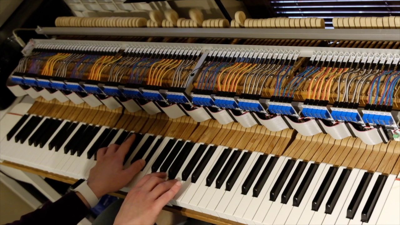
This GitHub project contains just the PCB design, the software and the mechanical considerations/descriptions of the controller. It may be used "as is" for anyone willing to recreate that project, or can evolve into a more advanced and improved design that can be used as a basis, or inspiration for other (hybrid or regular) MIDI-controllers, etc.
If you would like to discuss this project, there's a discussion thread on the PianoClack Forum
Brief description
Main Principle
The goal of the project is to detect the velocity of the piano hammers and trasnalate it into MIDI velocity. This is realized by using Vishay CNY70 optical sensors and Texas Instruments LM339 voltage comparators (LM339AD package).
The main principle of using voltage comparators to turn continuous analog signals into digital binary signals has been suggested by Marcos Daniel, a member of the PianoWorld forums. Everything else, including the multiplexing, PCB design, Teensy code and integration with a real grand piano action has been done by me.
- The CNY70 is an optical proximity sensor that consists of a photoemitter (a LED) and a phototransistor. The phototransistor will change its collector current depending on the proximity of subjects to the sensor
- By measuring the voltage drop created by the collector current on a resistor and comparing it to a reference voltage, we will know whether the subject is within a predefined proximity.
- A voltage comparator is a device that has two voltage inputs and a digital output. One of the inputs is a reference voltage selected through a trimpot and the other input is the phototransistor output voltage. If the phototransistor output voltage is higher than the reference voltage, the output of the comprator will be digital 1, otherwise it will be digital 0.
- Thus we can turn the continuous analog sensor signal into a discrete digital binary value that changes when the subject crosses a predefined distance
That is important because the LM339 voltage comparator is very fast when comparing two voltages. It takes just a few nanoseconds to switch its digital state. That allows for a very fast distance detection, or more specifically whether the hammer is either closer than, or farther than the preset distance point. In other words, the comparator will provide a digital output of 1 whenever the hammer crosses that distance and stays closer to the sensor, and will switch back to zero when the hammer crosses that point on its way back and moves away from it. By using that principle, we can avoid slow analog-to-digital conversion. (As you will see in the following paragraphs, if we scan through all 88 keys of a piano, and rely on just ADC to read the exact position of each hammer, might be a tricky task for many reasons. First, because most programmable controllers such as Arduino/Teensy, etc. have only a few (1 or 2) ADC chips and a single conversion takes microseconds which would cumulatively lead to inability to scan the entire keyboard without introducing huge latency and without missing the very fast hammer motion. And second, even if fast ADC-s are used, it will require that we multiplex analog signals and that's not a trivial task since there will be noise, etc.)
So, we can configure two preset distance points through two trimpots and use two voltage comprators. We will have two digital outputs from the two comparators and by measuring the time it takes for the hammer to pass between the two points (i.e. the comprators' outputs switch from 0 to 1), we can calculate velocity.
Additional details
Multiplexing
A standard way of reading multiple sensors through limited number of inputs is through multiplexing, i.e. using specialized chips that can (roughly speaking) switch between multiple inputs and then channel them through a single line. However a particular problem with this approach is that there is a switch delay and in this particular implementation scanning speed is of highest importance. To work around that, we can use a programmable controller with as many inputs as possible, and one such board is the Teensy USB Development Board. It has 58 digital input/output lines.
Grouping
We can gather multiple scanned notes into a group, then select a group, read all the sensor data (each sensor outputting two digital signals corresonding to two distances, as seen above), then switch to the nextg group, etc. until we read all notes. In the current implementation, for a 88-key piano, we have 3 binary signals per note (see below why 3 and not just 2) and a group is made of 5 notes. This means we have 18 groups (the last group only contains 3 notes and not 5):
18 groups x 5 notes = 90 notes (-2 unusued in the last group) = 88 notes
3 signals per note = 15 signals per group
18 groups x 15 signals = 270 binary signal lines
Now, if we can enable only one group at a time, we can then read the 15 signals from each group by reusing one and same 15 input signal lines. Thus we will have 18 group enable lines from the Teensy (outputs) and 15 input lines shared by all the 18 groups.
18 outputs + 15 inputs = 33 digital input/outputs.
Seems like we can go without using a mux/demux chips. Instead we will share inputs between groups. However, the problem is if we just wire the corresponding inputs of the groups, and since they will continuously generate differing signals ( one group can generate high signal at the same time another group will generate low signal), it means they will be short-circuiting themselves. To avoid that, we will use digital transceiver chips. A transceiver is a simple device that has a certain number of digital inputs and digital outputs. It will repeat on the outputs the same digital signal that it has on the corresponding input. Each transceiver chip also has an enable/disable line. When in disabled state, the outputs will be in high impedance state (regardless of input signals), and that is how we solve the problem of short-circuiting. For the current solution we use SN74LVC245A Octal Bus Transceivers With 3-State Outputs ( SN74LVC245ADWR package).
Circuit boards, wiring, power
There are three types of printed circuit boards
- Sensor PCB - these are very small PCB-s each containing a single CNY70 sensor and placed above each hammer shank base. In a 88-key piano there will be 88 of these. 5 of these connect to a single Note PCB.
- Note PCB - these are the group modules. Each one serves 5 Sensor PCB-s. Each Sensor PCB is connected through three wires (5V, signal, GND). There are three trimpots per sensor PCB, for setting the predetermined detection distances. The uppermost trimpot is for sensor 1 which is the closest distance to the hammer stop rail. The Note PCB-s also contain a jumper that is set to one of 18 positions to determine the group number of the Note PCB. Note PCB-s also have an IDC34 socket. The Note PCB-s should be aligned on a horizontal line and be connected through a single IDC34 cable that has 18 IDC connectors. Each Note PCB has two power sockets. Each power socket has three lines (5V, 3.3V, GND). The two power sockets are wired to each other so that one can be used as power input and the other as power output for chaining to the next Note PCB. There are two voltages because the CNY70 sensors and the comparators are powered by 5V, however the digital signals from the transceivers as well as their power supply is 3.3V. The Teensy 3.6 controller supports only 3.3V voltage (unlike Teensy 3.5 and older but they are slower)
- Teensy PCB - this one contains the Teensy controller, an IDC34 socket for controlling the Note PCB-s, power inputs/outputs to chain to the Note PCB-s, and possibility to connect other devices (e.g. a sustain half-pedal to the analog inputs.) It has s USB-B input that's used only for power input. The Teensy controller itself has a micro-USB for connection to the computer to trans
