SCIC
Project of Addison Elliott and Dan Ashbaugh to create IC layout of 32-bit custom CPU used in teaching digital design at SIUE.
Install / Use
/learn @addisonElliott/SCICREADME
SIUE CPU IC (SCIC)
Project of Addison Elliott and Dan Ashbaugh to create IC layout of 32-bit custom CPU used in teaching digital design at SIUE.
Note: This guide contains information based on Addison and Dan's experience with the Cadence tools during the 1 month period spent on the project. As a result, this guide may contain mistakes or incorrect information and pull requests are welcome to fix any issues.
Table of Contents
- SIUE CPU IC (SCIC)
- Table of Contents
- Overview - Block Diagram
- Setup
- Workflow
- Simulation
- Synthesis - Reports & Menus
- Place & Route
- Final Steps
- Results
- Workflow Commands List
- Future Work
- Simulating with Icarus Verilog
Overview
In the introduction class to digital design at SIUE, there is a simple CPU written in Verilog that is used for demonstration purposes. The design is discussed and simulated but never synthesized, whether it be on an FPGA or ASIC. In this project, we took the CPU from this class and created an ASIC design using the Cadence toolset making some minor changes and additions to the CPU itself.
Note: The original CPU from the digital design class can be found in the old_files folder of this repository.
Specifications:
- 1x 32-bit accumulator (AC)
- 32-bit instructions (1 word)
- Bidirectional I/O port (input = switches, output = LEDs)
- RAM
- ROM
- Non-pipelined implementation. Clocks per instruction (CPI) = 2
- 32-bit adder
- 4-bit opcode, 9 instructions, 16-bit address space
- Behavioral implementation
Instruction format for the CPU is as follows:
    31----28------------16-15----------------0
     Opcode    Unused            Operand
The updated CPU that we worked on contains the following instructions (bolded instructions are new):
| Instruction | Opcode | RTL | |------------------|--------|---------------------------| | Add | 1 | AC <= AC + mem(IR[15:0]) | | Shift Left | 2 | AC <= AC << mem(IR[15:0]) | | Shift Right | 3 | AC <= AC >> mem(IR[15:0]) | | Load immed. | 4 | AC <= IR[15:0] | | Load | 5 | AC <= mem(IR[15:0]) | | Or | 6 | AC <= AC | mem(IR[15:0]) | | Store | 7 | mem(IR[15:0]) <= AC | | Branch | 8 | PC <= IR[15: 0] | | And | 9 | AC <= AC & mem(IR[15:0]) |
Address range for the memory controller is as follows:
| Name | Range | Size (words) | Binary Range | |------|-------------|--------------|--------------------------------------------| | ROM | 0000-001F | 32 | 0000 0000 0000 0000 -> 0000 0000 0001 1111 | | RAM | 0020-003F | 32 | 0000 0000 0010 0000 -> 0000 0000 0011 1111 | | I/O | 0040-005F | 32 | 0000 0000 0100 0000 -> 0000 0000 0101 1111 |
Test ROM Program to fully test all the instructions:

Block Diagram

Setup
Note: This was run using Dr. Engel's special workflow with custom TCL scripts. You must do this using the lab machines with their custom scripts in order for this tutorial to work.
Begin by logging into a VLSI lab machine in EB3009 and then open a terminal. Run the following commands to get your terminal setup with Dr. Engel's custom scripts. These commands only need to be run once each time you open a terminal to setup your environment correctly.
cds_ams
cd $PHOME
setup_edi
Navigate into verilog.src and clone the project repository with the following commands. Note: If you are wanting to push changes back to the repository eventually (requires write access), then you must use the following URL rather than the one given below https://<GITHUB_USERNAME>@github.com/addisonElliott/SCIC.git.
cd verilog.src
git clone https://github.com/addisonElliott/SCIC.git
The directory verilog.src contains all Verilog projects that are going to be simulated or synthesized using Cadence. This is a custom directory structure setup by Dr. Engel to adhere to his specific workflow. The purpose is to standardize where projects are located for ease of use. Cloning the repository only needs to be done once because afterwards it will be stored on your machine. But, if you want to pull new changes from the repository, you can do so with the command git pull origin master. You must be inside the directory to run the git command (or any git commands for that matter).
Next, one more once-per-machine step must be done. There is a TCL and SDC file that is expected to be in a different directory to adhere to Dr. Engel's workflow. Since we wanted to make these files tracked by our GitHub repository, we place these files in the repository and create symbolic links (i.e. symlinks) to these locations. Run the following two commands to create symlinks for the TCL and SDC file in the appropriate directory.
ln -s $PHOME/verilog.src/SCIC/env.SCIC.tcl $PHOME/env_files/
ln -s $PHOME/verilog.src/SCIC/SCIC.sdc $PHOME/verilog.src/sdc/
If you want to verify that the symlinks were made, take a look at the figure below where I used the ll (alias to ls -l) command to achieve this. You can see that the output shows a symlink pointing to the repository location.

Once the repository is cloned and setup, one remaining command must be called. This command must be called each time a terminal is opened to set the current base project. sb is a script written by Dr. Engel and is short for set base to set the base project. The argument to this script is the name of any project contained in the verilog.src folder. To see the current project, you can type b for the base project. The workflow commands used below use the current "base project" to perform their respective actions on.
sb SCIC
Workflow
The general workflow for synthesizing a Verilog project to an IC can be seen below. Preceding the RTL simulation is developing the Verilog module, general setup of the project and creating the SDC & environment TCL file. While developing your project, it is extremely common to encounter an error in one of the steps, in which case you will correct the error and restart the workflow.

Simulation
The first step of any design is to simulate the Verilog code using a testbench to ensure that it is performing the way it is designed. There are three cases throughout the workflow that a simulation is performed.
- RTL Simulation (rtl)
- Ideal simulation with no delays included. Used to verify design functionally works
- Post-Synthesis Simulation (syn)
- Performed after synthesis and includes propagation delay for gates (no wiring delay is included)
- Post-PNR Simulation (pnr)
- Performed after place & route and includes the wiring delay as well as the propagation delay for gates
- This is the final simulation and should mimic the real-life waveforms present on the chip
The simulation in each case can be ran the same way except for one minor change. The env.SCIC.tcl file must be edited to set the simulation mode to the desired mode. Editing the file can be done using your favorite text editor (gedit, vim, nano, etc). Change the line SIM_MODE to the desired mode.

Run the following commands to simulate the design. There is no need to run the cd command if you are already at $PHOME.
cd $PHOME
sim
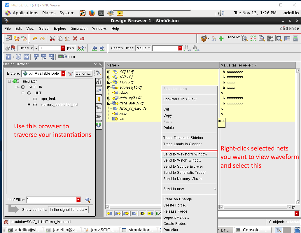
Cadence's simulator software SimVision should pop up. There will not be a detailed discussion on using SimVision, since it is fairly self explanatory. You can navigate through the Design Browser on the left to find wires that you want to add to the waveform window. You can add them by right-clicking and select "Send to Waveform Window". Once you have all the wires you want in the Waveform Window, you cans elect the "Play" icon in the toolbar to run the simulation. There is a bar at the bottom that can be dragged to change at what point of time you are viewing. See screenshots below for details on the process described.
Note: To make your life easier, you can save your current setup in the waveform window by clicking File -> Save Command Script and save the file as restore.tcl which will automatically be loaded each time a simulation is ran. This saves you the trouble of having to add the same wires to the waveform window.
See the results section for screenshots of what you should see for this step (Click here)

Before running a Post-Synthesis and Post-PNR simulation, you must type the following command to create special testbenches that include delay information. The delay information from the synthesis and place & route step are stored in a Standa
