SmartdoorF455
C++ project using a RealSenseID camera for facial authentication to trigger a door buzzer on a Raspberry Pi
Install / Use
/learn @JoergWall/SmartdoorF455README
smartdoorF455 - door opener with biometric facial authentication
<p align="right"> <!--- <a href="./README_DE.md" rel="noopener">GERMAN VERSION</a> --> <p align="center"> <a href="" rel="noopener"> <img width=251px height=513px src="images/small/01_mounted_smartdoorF455_side-view.JPG" alt="smart door opener with facial authentication"></a> </p> <h3 align="center">smartdoorF455</h3> <div align="center">![]()
![]()
![]()
<p align="center">With the introduction of the iPhone X in September 2017, Apple introduced authentication with biometric facial features as a reliable technology in our everyday lives. With this project, we want to bring this process as a door opener from the smartphone to the smart home. <br> </p>
📝 Table of Contents
- About
- Getting Started
- Prerequisites
- Functionality
- Hardware Setup
- Wiring
- Presence Sensor
- Case Installation
- Software Installation
- Usage
- Teach faces for authentication
- System Configuration
- Open Sesame
- Camera Security
- End of Life of Intel ReaSenseID F455
- Troubleshooting
- Ideas for Changes and Enhancements
- Conclusion
- Video
- Built Using
- Author
- Acknowledgments
🧐 About <a name = "about"></a>
Early 2021 Intel announced the RealSense ID F455 camera, which picks up the principle of 3D facial authentication and offers makers an interesting product for integration into self-constructed solutions. The camera scores with extensive documentation, an open source SDK for Linux, Windows and Android as well as the languages C, C++, C# and Python. In contrast to Apple, it allows the authentication of more than one person, whose profiles are either stored centrally on a server or in a database on the camera itself. The RealSense ID F455 is therefore the perfect candidate for opening our front door using 3D face recognition with a similarly low error rate as Apple's iPhone.
<a href="" rel="noopener"> <img width=50% height=50% src="https://newsroom.intel.com/wp-content/uploads/sites/11/2021/01/Intel-RealSense-ID-2-scaled.jpg" alt="Intel RealSenseID F455 Announcement"></a>🏁 Getting Started <a name = "getting_started"></a>
If you think about building a smart door opener with 3D facial authentication, please first look out for an IP interface to the door buzzer. This is the tricky part for a possible replica of this application and this may require creativity at your end, as the requirements are very different from door to door. We found a Siedle brand bus-based door opener for this project. Depending on the door intercom and the IP gateway, the code for must be adjusted accordingly. We have marked this in the code with "TRIGGER DOOR OPENER START" and "TRIGGER DOOR OPENER END". If you do not use an MQTT for the communication to open the door, you can comment out the line #define MOSQUITTO_IN_USE, or remove or adapt the lines enclosed with these #ifdef's.
🔨 Prerequisites <a name = "prerequs"></a>
The hardware required for this maker projekt is about ~500 USD in total not including an IP gateway to the door buzzer.
- Intel RealSense ID F455 camera
- Raspberry PI 4B, >= 4 GB RAM running Raspberry Pi OS
- Micro SD card >= 16 GB
- 5V power supply e.g. Meanwell IRM-60-5ST 5V 10A
- casing e.g. outdoor lamp with sensor Severina by Lindby
- RGB LED 64x32 P2,5 Matrix with 160x80 mm dimensions e.g. Adafruit 5036
- E18-D80NK IR photoelectric barrier
- 10 kΩ pull up resistor
- 40 pin GPIO ribbon cable or 20x female/female jumper cable
- 4x 40mm, 4x15mm, 2x 10mm M3 spacer bolts for the LED Matrix
- 8x M3 screw nuts for fastening the spacer bolts to the housing plate
- 4x M2,5 12mm screws for attaching the Raspi to the housing plate
- ¼ inch screw for fastening the camera on the underside of the housing
- IP-based interface to the door buzzer. This code assumes an MQTT interface as we found a "Siedle Bus" based door intercom and use a MQTT Siedle gateway from Oskar Neumann
- Optional: Geeek Pi Raspberry Pi 4 Armor Case
- Optional: Adafruit RGB Matrix Bonnet
- Optional: 40 Pin Pitch Stacking Header – to increase the distance between the matrix bonnet and the board so that it protrudes over the armor case
- Optional: PIR Sensor HC-SR 501 as an alternative presence sensor for the photoelectric barrier
Functionality <a name = "functionality"></a>
The smart door opener has replaced the outdated entrance lighting and is therefore housed in the casing of one. The system is only supplied with main voltage and communicates via the in-house WIFI. It must therefore be ensured that the location of the admission control has an appropriate WIFI reception.

smart door opener in the guise of an outdoor lighting
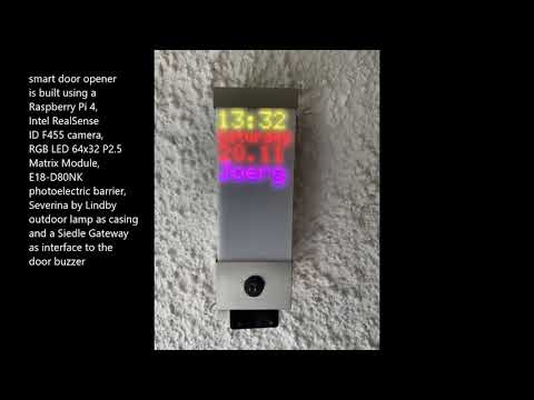
Since the camera itself does not have a presence detector, it is triggered by an infrared reflex light barrier. The person asking for admission wipes their hand past the light barrier or comes a little closer with their face. A faint red glow from the infrared illuminator of the upside-down camera at the bottom of the case can be seen briefly. The camera now projects invisible infrared points with a wavelength of 850 nm onto the face, records them with two full HD cameras integrated on the side and uses them to form a three-dimensional point cloud, which it compares with the stored face profiles via AI inference. The camera needs less than a second for this authentication process and transfers the result - in the positive case the name of the recognized person - to the Raspberry Pi computer via USB cable. Since we only use one camera, these profiles are stored locally on the camera. For authentication with multiple accesses, the camera offers a server mode in which the access profiles are stored on a central server and can thus be used by multiple cameras. If the authentication is positive, the name of the recognized person is shown on the LED matrix display for a few seconds and the door is opened via MQTT command via WIFI. When idle, the LED matrix panel shows the time, the day of the week and the current date. You can find a demonstration of how it works via YouTube video here:
Youtube - how the smart door opener with 3D face recognition works
Hardware Setup <a name = "hardware_setup"></a>
A Raspberry 4B with Raspberry PI OS aka Raspian is used as the host computer. We decided on an outdoor light in a stainless steel housing for the housing, which gives off an inconspicuous image when placed in front of the front door. In addition to the Raspi, it contains a 5V power supply with 50 watts of power, a retro-reflective sensor and an Adafruit 5036 LED matrix display with a resolution of 64x32 RGB LEDs. This is attached to the base plate of the housing using 4 spacer bolts, each with an added length of 55 mm (40 mm + 15 mm). The matrix module has a thickness of 15 mm, resulting in a distance of 70 mm between the base plate and the frosted acrylic glass. To ensure that the LED matrix content does not become too blurred due to the satin finish, it is important that the LED matrix module is in direct contact with the acrylic glass.
Before the structure is integrated into the dismantled lamp housing, the components are wired as a prototype and the functionality of the individual components and the system is tested.

first test in the prototype structure
Wiring <a name = "wiring"></a>
There are 2 options for connecting the RGB matrix display to the Raspberry PI:
- Adafruit RGB Matrix Hat/Bonnet:
This plug-in board offers tidy cabling via the HUB75 connector, which is included with the LED matrix module. In order to avoid that the plug-in board does not get in the way of the Raspi Armor Case, it must be raised using a 40-pin pitch stacking header. This creates the disadvantage of a higher design of approx. 6 cm. Since the Raspi is installed in the lower part of the housing opposite the sensor, this is OK for using the PIR sensor HC-SR 501, but leads to a collision when assembling the E18-D80NK IR light barrier with a housing length of 5.5 cm of the lamp housing. Therefore, when using the E18-D80NK light barrier, we recommend either the discrete wiring shown below or swapping places - power supply unit in the lower part of the housing, Raspi in the upper part!
The Raspi is powered via the jack plug or the screw terminals on the Adafruit Bonnet. In addition, the Adafruit Bonnet uses other GPIO Ports for communication, so in Adafruit Bonnet case we use GPIO 19 for the presence sensor. A jumper cable for the sensor output must therefore be soldered onto the bonnet.

Wiring with Adafruit Matrix Bonnet to Pitch Stacking Header soldered to GPIO19 with jumper wire over armor case
- Discrete wiring with 40-pin GPIO ribbon cable or female-to-female jumper cable <a name = "discrete-wiring"></a>

discreet wiring, LED matrix with 55mm spacer bolts wrap around Raspi and power supply
 ‚
*discrete wir
‚
*discrete wir
Related Skills
node-connect
342.5kDiagnose OpenClaw node connection and pairing failures for Android, iOS, and macOS companion apps
frontend-design
85.3kCreate distinctive, production-grade frontend interfaces with high design quality. Use this skill when the user asks to build web components, pages, or applications. Generates creative, polished code that avoids generic AI aesthetics.
openai-whisper-api
342.5kTranscribe audio via OpenAI Audio Transcriptions API (Whisper).
qqbot-media
342.5kQQBot 富媒体收发能力。使用 <qqmedia> 标签,系统根据文件扩展名自动识别类型(图片/语音/视频/文件)。
